Code: NCS_POL_01
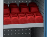
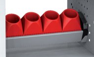
Folded shelf for NC holders NCS POL 0140.75 Eur without VAT
(49.31 Eur with VAT)
Folded shelf for NCS cabinets to store plastic beds for NC tools.
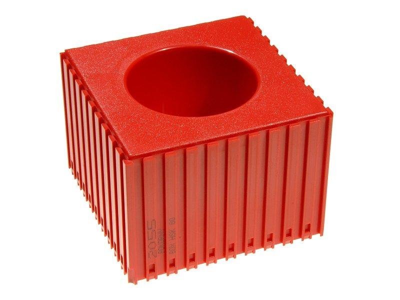


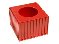
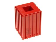
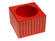
Code: 2055 HSK 80
Plastic bed of CNC tool HSK 80, also usable for KM, WDX and UTS systems. The main benefit is clarity, order and cleanliness in the full description and parameters
Plastic bed of CNC tool HSK 80, also usable for KM, WDX and UTS systems. The main benefit is clarity, order and cleanliness in the workplace. You can create any combination of individual elements. The elements are connected using a dovetail joint. Color red RAL 3020 or blue RAL 5015.
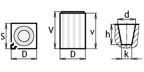
| Dimension D: | 102 mm |
|---|---|
| Dimension S: | 102 mm |
| Dimension V: | 72 mm |
| Dimension d: | 60.8 mm |
| Dimension in: | 70 mm |
| Dimension h: | 44.5 mm |
| Dimension k: | 57 mm |
| Number of cavities: | 1 |
| Warranty (years): | 2 |
| Manufacturer: |

|
Code: NCS_POL_01
Folded shelf for NC holders NCS POL 0140.75 Eur without VAT
(49.31 Eur with VAT)
Folded shelf for NCS cabinets to store plastic beds for NC tools.
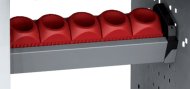
Code: NCS_POL_02
Folded shelf for NC holders NCS POL 0234.29 Eur without VAT
(41.49 Eur with VAT)
Folded shelf for NCS cabinets to store plastic beds for NC tools.
Code: NCV_KAS_01
Plastic bed carrier NCV KAS 0131.42 Eur without VAT
(38.02 Eur with VAT)
Removable plastic bed carrier 100 x 100 mm, load capacity 40 kg.
Code: NCV_KAS_02
Plastic bed carrier NCV KAS 0231.42 Eur without VAT
(38.02 Eur with VAT)
Removable plastic bed carrier 80 x 80 mm, load capacity 40 kg.
Code: 2013 M1
Morse 2013 M1 CNC Tool Plastic Bed1.83 Eur without VAT
(2.21 Eur with VAT)
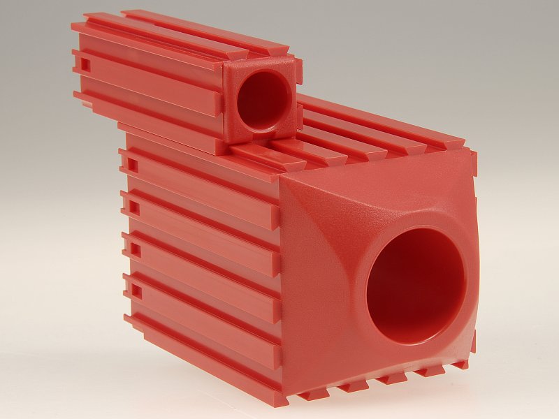
The box is intended for storing and storing clamps, cutters, drills, reamers and other tools with a Morse 1 taper shank. The main benefit is clarity, order and cleanliness in the workplace. You can create any combination of individual elements. The elements are connected using a dovetail joint. Choice of red RAL 3020 or blue RAL 5015.
Code: 2000 D3
Plastic CNC bed for milling cutters with a cylindrical shank of 3 mm2.59 Eur without VAT
(3.13 Eur with VAT)
The box is intended for storing miniature cutters with a cylindrical shank with a diameter of 3 mm, grinding bodies and other small tools. You can create any combination of individual elements. The elements are connected using a dovetail joint. Choice of red RAL 3020 or blue RAL 5015.
Code: 2310 20x20
CNC plastic bed for storing lathe knives 20 x 202.91 Eur without VAT
(3.52 Eur with VAT)
Bed with a 20 x 20 holder profile. The main benefit is clarity, order and cleanliness in the workplace. You can create any combination of individual elements. The elements are connected using a dovetail joint. Choice of red RAL 3020 or blue RAL 5015.
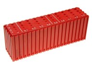
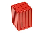
Code: 2023 D1-D4.9
Plastic box for storing drill bits D1-D4,96.04 Eur without VAT
(7.31 Eur with VAT)
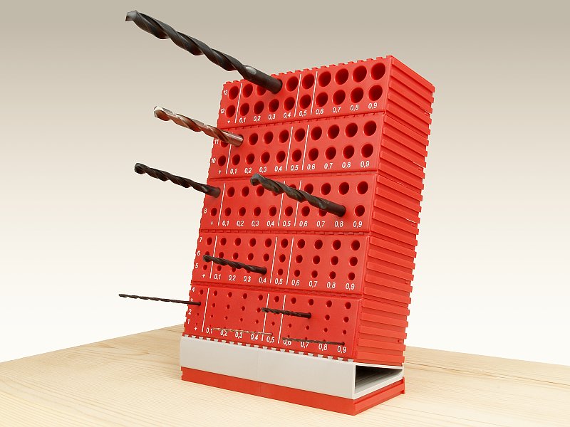
The box is designed to store drill bits with diameters of 1-4.9 mm. Gradation of individual hole diameters makes it easier and faster to find and reinsert the drill into its place. Cavity depth 12–20 mm, color red RAL 3020.
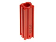
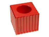
Code: 2051 HSK 32
Plastic bed of CNC tools HSK 322.91 Eur without VAT
(3.52 Eur with VAT)
Plastic bed for CNC tools HSK 32, also usable for KM, WDX and UTS systems. The main benefit is clarity, order and cleanliness in the workplace. You can create any combination of individual elements. The elements are connected using a dovetail joint. Color red RAL 3020 or blue RAL 5015.
Code: 2052 HSK 40
Plastic bed of CNC tools HSK 402.91 Eur without VAT
(3.52 Eur with VAT)
Plastic bed for CNC tools HSK 40, also usable for KM, WDX and UTS systems. The main benefit is clarity, order and cleanliness in the workplace. You can create any combination of individual elements. The elements are connected using a dovetail joint. Color red RAL 3020 not blue RAL 5015.
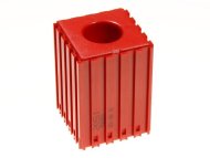
Code: 2053 HSK 50
Plastic bed of CNC tools HSK 504.56 Eur without VAT
(5.52 Eur with VAT)
Plastic bed for CNC tools HSK 50, also usable for KM, WDX and UTS systems. The main benefit is clarity, order and cleanliness in the workplace. You can create any combination of individual elements. The elements are connected using a dovetail joint. Color red RAL 3020 or blue RAL 5015.
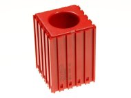
Code: 2054 HSK 63
Plastic bed of CNC tools HSK 634.56 Eur without VAT
(5.52 Eur with VAT)
Plastic bed for CNC tools HSK 63, also usable for KM, WDX and UTS systems. The main benefit is clarity, order and cleanliness in the workplace. You can create any combination of individual elements. The elements are connected using a dovetail joint. Color red RAL 3020 or blue RAL 5015.
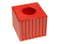
Code: 2056 HSK 100
Plastic bed of CNC tools HSK 1005.81 Eur without VAT
(7.03 Eur with VAT)
Plastic bed of CNC tools HSK 100, also usable for KM, WDX and UTS systems. The main benefit is clarity, order and cleanliness in the workplace. You can create any combination of individual elements. The elements are connected using a dovetail joint. Color red RAL 3020 or blue RAL 5015.
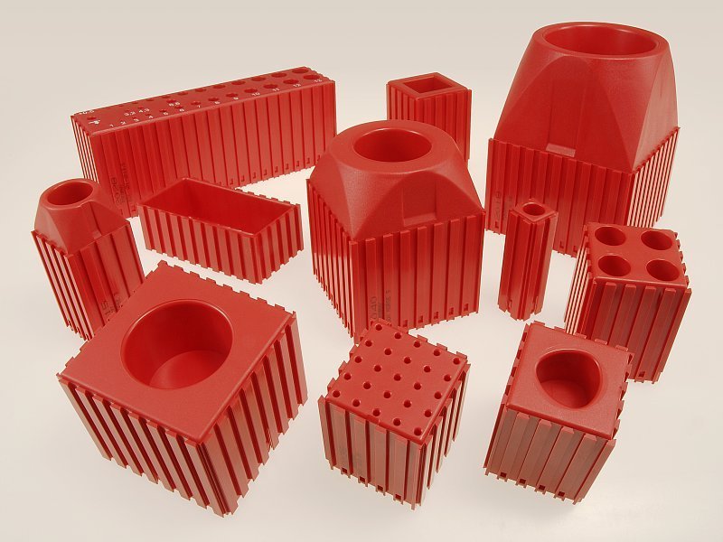
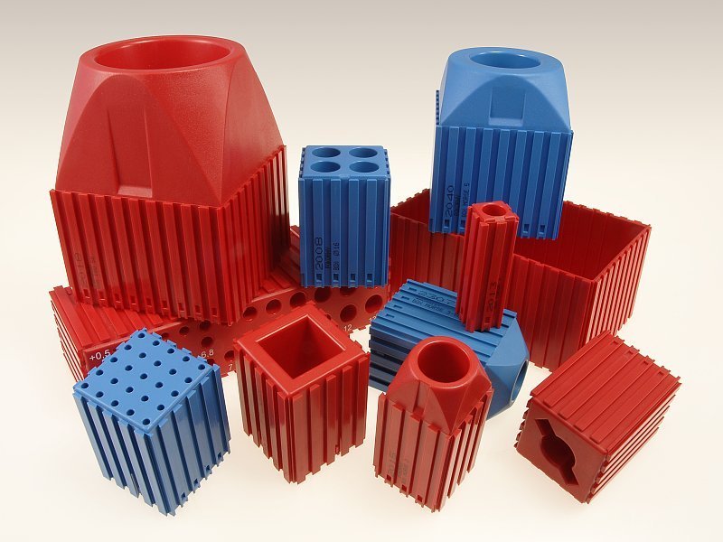
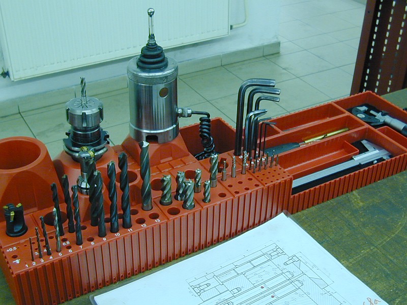
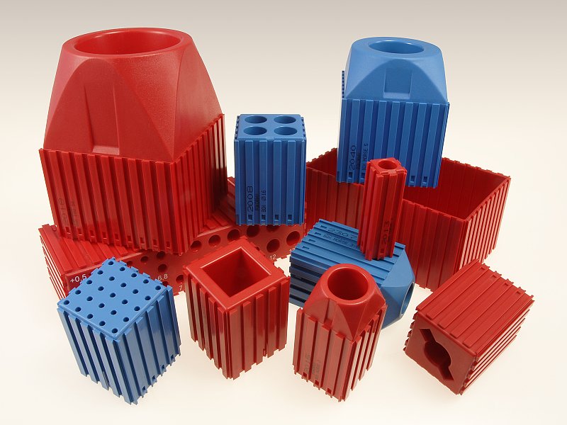
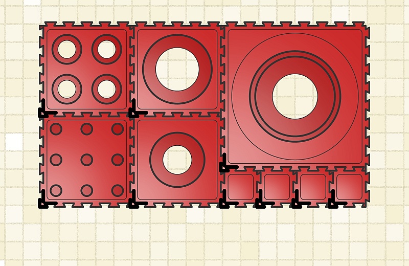
The building block system of boxes is used for the orderly and clear storage of tools at workplaces and in warehouses.
 |
 |
|
| Sample 1 | Sample 2 |
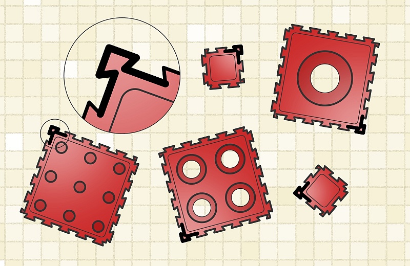
The boxes are made of ABS material in two colors, red (RAL 3020) and blue (RAL 5015). You can find a detailed description of individual parts in the online catalog.
 |
 |
|
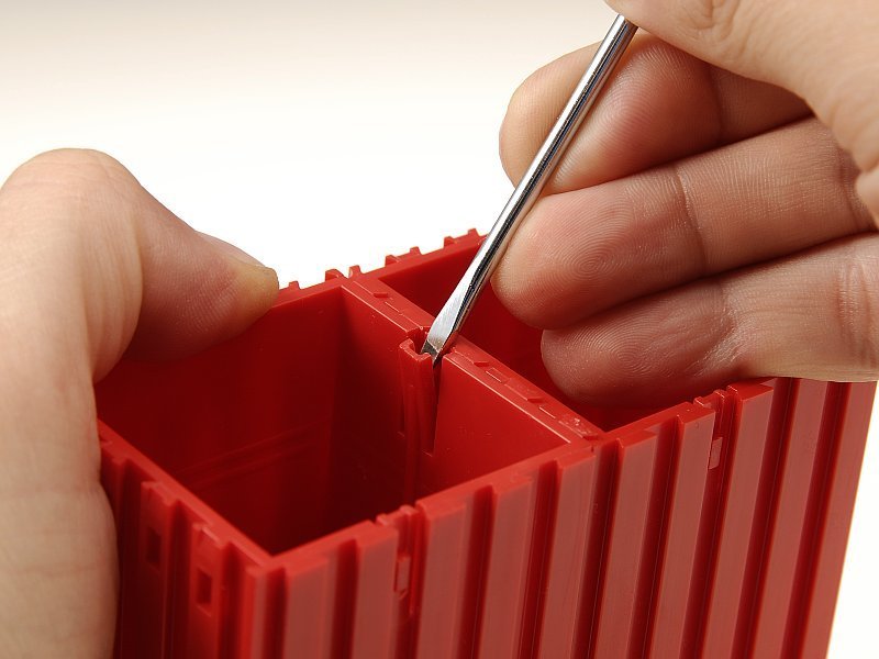
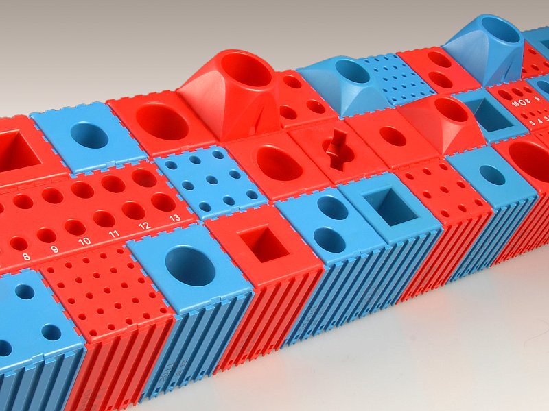
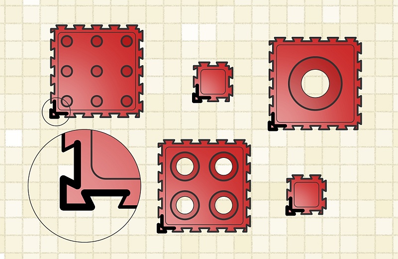
The boxes are designed as a highly variable workshop kit. They are connected using a dovetail groove in any assembly. A fuse is used to prevent the assembly from being disassembled. If you need to disassemble the assembly again, the fuse must first be released for the individual parts.
 |
 |
|
| Dovegrooving | Flexible fuse |
All parts of the kit can be combined not only with each other, but also with boxes, panels and expansion elements.
When creating reports, follow the instructions. It is especially important to maintain the correct orientation of the kit parts during assembly. Incorrect orientation will make other parts impossible to connect.
You can download the instructions here!
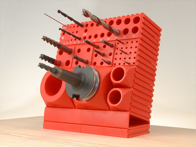
Among the components of the kit you will find special boxes for drill sets and boxes for storing IMBUS keys or an electrode holder.
 |
 |
|
| For drill sets | For IMBUS keys |
In the boxes for drills, the diameters of the storage cavities are graduated in 0.1mm increments and have labels. The description speeds up the finding of the necessary drill, and the grading helps to correctly place the drill back in its proper place.
There are two simple rules to follow when creating reports. This will prevent difficulties and avoid a bad experience.
Users without previous experience are advised to take stock of the overall arrangement of the assembly on squared paper before starting work. This can be especially useful when combining parts with different join modules.
 |
 |
|
| 1. Messy boxes | 2. Correctly shot boxes |
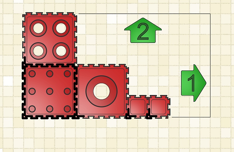
On each box you will find four different corners. Only one of them has an arrow shape and is called a positioning corner.
First rotate each element of the system correctly before connecting it to the assembly. The positioning corner should point to the lower (or closer) left corner of the resulting assembly (see Fig. 2).
 |
 |
|
| 3. Connection order | 4. The resulting assembly |
When creating an assembly, always first connect the individual boxes to the whole in the crosswise direction from left to right (direction 1). If the row is wide enough, you can connect other parts in the longitudinal direction from front to back (or bottom to top, direction 2).
Following the correct connection order means that you start at the near left (or lower left) corner of the assembly and end at the far right (upper right) corner of the assembly.
jak-na-boxy-cz.pdf (1.11 MB) - Instructions for connecting boxes for printing